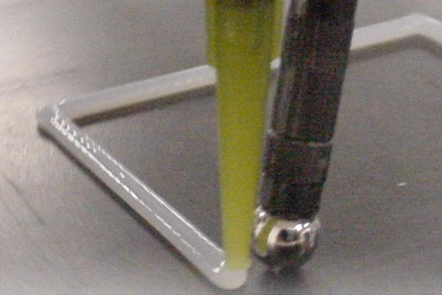
Replacing O-rings with FIP gasket application
January 1, 2022I need to preface this with the following: I am not a machine safety expert! Each machine installation has its own unique operator/machine interface considerations and the most valid assessments are made on site.
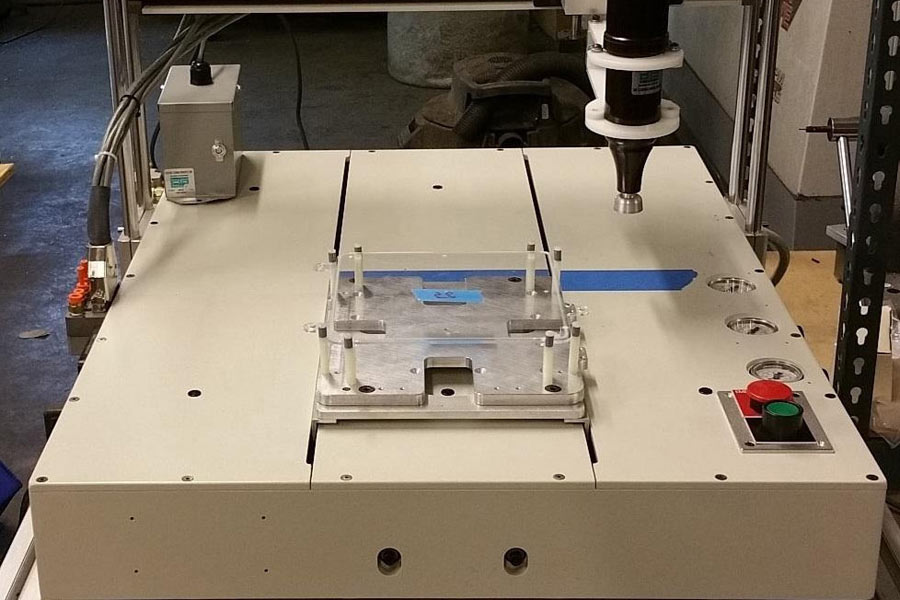
That said, one common consideration involves split bridge Cartesian robotics applications and their given work envelope versus their machine footprint.
First, what is a split bridge system? These actually tend to be some of the safest pieces of production equipment available – at least in our experience. In the split bridge design, the product being worked on rides front to back on the Y axis while the Z is mounted to the X and placed as a bridge over the Y. This tends to be a safer design as the mass of the X and Z is divorced from the Y. In most other designs, the Z rides on the X which rides on the Y. The Y motors then need to have a high force capability in a typical axis-on-axis system. In a split bridge system the product rides independently on the Y axis and so the only real factor when considering motor force is the maximum weight of the product riding on the stage. The Y motor in a split bridge design can easily be a fraction of the size of a motor in an axis-on-axis system. In a split bridge design it is not uncommon to have motors operating at less than 150oz-in of torque while for axis on axis machines, the torque requirements for equivalent system performance are 3x to 4x higher.
From a safety perspective, in a split bridge design, the “business end” of the machine (dispense valve, pick-and-place tooling, etc) is typically in the middle of the Y (half way from front to back). You have to reach half way into the work envelope to get near the business end on such machines. On every other design, the end effector (the “business end”) travels the entire work envelope and so inherently the operator is closer to the business end.
And so the tendency of machine builders to declare work envelopes larger than the overall footprint of the machine negates one of the key advantages of the split bridge design – safety. If a machine builder gives a work envelope of 700mm, and the base is only 850mm, that means the pallet on such a system will extend past the machine by ((700 x 2) – 850)/2 or 275mm both front and back of the machine! For those in the imperial world, the pallet will move rapidly to wherever its told which includes overhanging the boundaries of the machine by 10.8 inches in this example.
On our CP16 systems, our base depth is 31″ and our bumper to bumper travel on the Y is 15.5″. We regard split bridge systems with work envelopes in the Y greater than twice the Y footprint to be at the very least less safe. Or, If a system has an 850mm depth, the machine work envelope should be curtailed to 425 mm when applications are set up on the factory floor.
In production environments, no-split bridge systems should really have either passive protective measures (sides, IR curtains, etc) or be used in such a way that regular operator interactions are protected. When such systems are integrated into conveyor lines or index tables, the safety systems of these material handling systems can often integrate back into the dispensing systems. For example our ICP system when integrated over a dial cannot run into an operator unless the machine is being serviced in a non production manner. In such systems the protective measures need to factor in the entire ensemble of automation.