Quality Control with New Precision Technology
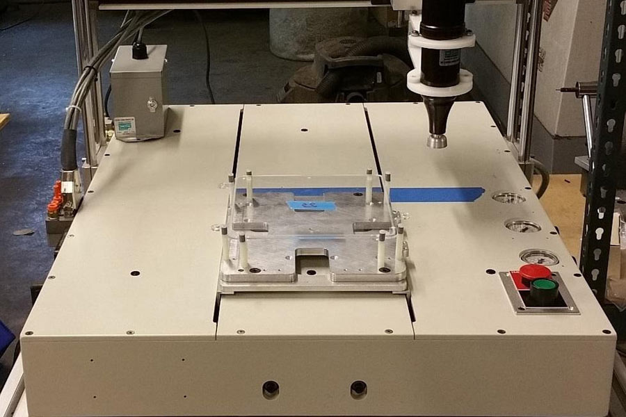
January 22, 2021Machine footprint vs work envelope
January 4, 2022


In the past, we here at New Precision often encounter existing applications where the desire is to replace an existing O ring in an assembly with a FIP (form-in-place) version. This is a goal with various complications and designers should tread cautiously before making this leap.
The desire to utilize FIP gasketing is understandable. It is possible that an assembly might use many different O ring diameters and thicknesses. This represents potential issues with inventory count, product aging, errors in inventory placement, and inventory overhead cost – all of which can be eliminated with FIP dispensing. Inherently placing O-rings is a manual process and care must be taken to place the O-ring in the proper location and not damage it during placement. Traditional o-rings have no adhesive component and so they can shift position post-assembly and then lose their ability to perform their function. All of these contribute to make FIP gasket dispensing seem like a perfect solution.
The reality, however, is that for optimal production quality and consistency, components must be designed to contend with alternate set of design challenges FIP introduces. There are actually very few instances (none?) where a FIP gasket can replace an O-ring without adapting an original design or specifically designing for FIP gasket application at the outset.
At the root of the issue is that the cross section of a traditional, uncompressed O ring is a circle. When you place the O-ring in a channel or groove with square corners (floor to wall) there are four gaps in the uncompressed state when you factor in the mating surface. These gaps provide an escape zone as the mating surface is engaged. In a properly designed application the gasket compressed portion will not exceed the gap areas and the mated faces will come into full contact. If a tighter seal is required, the durometer of the O-ring can be selected to meet the seal requirements.
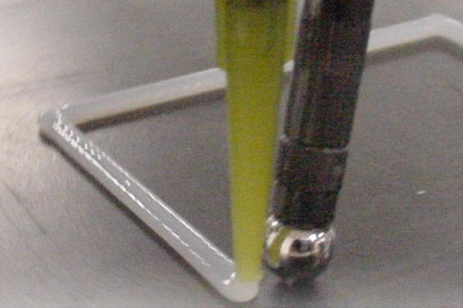
If you were to take the same O-ring application and attempt to use FIP, at the very least you lose two of the four corners described previously, and so you have half of the escape zone that a traditional O-ring would have. There is a side issue with the shear generated between the channel sides and the FIP version, but that affects adhesion to the substrate – a separate issue.
With this in mind, however, it is perfectly reasonable to redesign to accommodate the FIP concerns – either slightly wider channels or replacing channels with standoffs. If you take a look at our gasket design tool – or contact us – you can see alternative methods of channel design for a given gasket profile. These tools can be used to optimize channels and standoffs for FIP use.